

-
Welcome to 4Runners.com!
You are currently viewing as a guest! To get full-access, you need to register for a FREE account.
As a registered member, you’ll be able to:- Participate in all 4Runner discussion topics
- Transfer over your build thread from a different forum to this one
- Communicate privately with other 4Runner owners from around the world
- Post your own photos in our Members Gallery
- Access all special features of the site
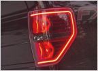 Saw New Tail Lights Today But Can't Find - Help?
 Baja Designs vs Extreme LED light bar in C4 LoPro Bumper?
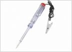 Multi-meter question
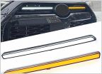 Novice- Need Help Wiring
 Change DRL lights to amber?
DIY Chase Lights
Discussion in 'Lighting' started by Cis915, Feb 2, 2024.
Products Discussed in


