1. Welcome to 4Runners.com!

    You are currently viewing as a guest! To get full-access, you need to register for a FREE account.

    As a registered member, you’ll be able to:
    • Participate in all 4Runner discussion topics
    • Transfer over your build thread from a different forum to this one
    • Communicate privately with other 4Runner owners from around the world
    • Post your own photos in our Members Gallery
    • Access all special features of the site
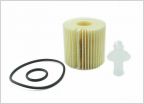
Auxiliary high-beam tap to relay, lights flickering in DRL mode

Discussion in '5th Gen 4Runners (2010-2024)' started by mynameistory, Mar 3, 2020.

  1. Mar 3, 2020 at 5:40 PM
    #1
    mynameistory

    mynameistory [OP] New Member

    Joined:
    Dec 28, 2017
    Member:
    #5208
    Messages:
    1,140
    Gender:
    Male
    First Name:
    Tory
    Vehicle:
    The same 4Runner everyone has
    Hi everyone,

    I'm pretty much done wiring up my auxiliary high-beam lights. I used a fuse tap to trigger the relay, but there's a problem. As you might know, the 5th gen 4Runner uses PWM (pulse width modulation) to dim the high-beam circuit for DRL (daytime running light) use. Instead of lowering the voltage, it instead pulses the circuit rapidly for the high-beams to glow dimly. The problem with this is that it can still intermittently ping the relay tapped in, causing my auxiliary beams to occasionally flicker when the stalk is set to DRL. The lights work exactly as designed when flicking the high-beam switch, as desired.

    I am already using a switch inline to turn off the auxiliaries when not needed. Does anyone know if a way to suppress the relay triggering inadvertently during DRL mode? An inline capacitor or filter, something like that?

    Thanks,
    -Tory
     
  2. Mar 3, 2020 at 5:40 PM
    #2
    mynameistory

    mynameistory [OP] New Member

    Joined:
    Dec 28, 2017
    Member:
    #5208
    Messages:
    1,140
    Gender:
    Male
    First Name:
    Tory
    Vehicle:
    The same 4Runner everyone has
    So, I found this thread that describes a very similar situation:

    https://www.electro-tech-online.com/threads/filtering-pwm-on-12v-circuit.128439/

    One of the posters provides a diagram for the solution, seen here:

    [​IMG]

    I'm going to order some parts to build little protoboards with this filter, and try various capacitors to find one that works. If there's any interest, I might make some extra for anyone looking to run auxiliary high beams without the PWM pinging the relay in DRL mode.
     
  3. Mar 4, 2020 at 12:22 AM
    #3
    1bad2k

    1bad2k New Member

    Joined:
    Feb 14, 2018
    Member:
    #5490
    Messages:
    62
    Gender:
    Male
    First Name:
    Sam
    Vehicle:
    2000 SR5 4x4 4R
    Cool! I think I'd be interested. Shoot me a PM when you get it figured out lol.
     
  4. Jan 7, 2024 at 12:49 PM
    #4
    PJSnow

    PJSnow New Member

    Joined:
    Dec 11, 2019
    Member:
    #12291
    Messages:
    149
    First Name:
    PJ
    New York
    Vehicle:
    2018 Cavalry Blue TRD Pro
    I came across this thread after reading your "not-a-build" thread. I am in the process of trying to reorganize my auxiliary light wiring by starting with schematic diagrams. I will preface by stating I have very little electrical/wiring experience but I am eager to learn to keep this as organized as possible. Having the ability to trigger the auxiliary lighting with a flick of the high beam stalk (as well as anytime with separate switches) would be a great feature but clearly it is not as simple as tapping the wire. Your build thread has a nice schematic of the high/low switch, but if I understand correctly, the PWM signal will still flicker the auxiliary lights in high mode. That post was also focused on the 2021+ headlight retrofit which I have not been able to do yet.

    My questions:
    - Were you able to figure out this filter? I assume it would be an in-line component? If you create any extras, I would be interested as well.
    - Would I be able to use a regular single push switch to go from anytime control to high beam control? I don't understand the need for the "off" position in the dual switch setup you have and you even mention "the circuit can still be exposed if I forget to turn the switch off". I figure two positions (on or off) may simplify it? This may require the use of the 87a pin but that is where my automotive wiring understanding falls short...
    - Since the high beam fuse is in the engine bay, does it make sense to mount the high/low control relay in the passenger compartment? I assume that would reduce the number of wires having to pass through the fire wall. This would also require a distribution block behind the dash to pass the signal to the individual auxiliary light switches. As stated previously, I am trying to draw wiring schematics to plan my wiring project for an organized result.
     
    mynameistory[OP] likes this.
  5. Jan 7, 2024 at 3:45 PM
    #5
    mynameistory

    mynameistory [OP] New Member

    Joined:
    Dec 28, 2017
    Member:
    #5208
    Messages:
    1,140
    Gender:
    Male
    First Name:
    Tory
    Vehicle:
    The same 4Runner everyone has
    I'm not sure of this, but I believe the PWM duty cycle is at 100% when high-beams are selected, so it's effectively a steady voltage with no buzz.

    I ordered the parts to make my own filters, but I never got around to making them. In the meantime, I just leave the switch in the OFF position to avoid buzzing the relay (rarely do I need the aux high-beams in daily driving).

    Most applications that I see a 5-pin being used to control 2 different circuits, and the relay switches between them. I'd have to think a bit about how to use a single SPST (push) switch to do both on anytime and high-beam trigger. The point of using the SPDT switch (with a central OFF position) is that I can use a single 4-pin relay and switch slot to have 3 functions. OFF is for when I don't need auxiliary high-beams, which is the majority of the time.

    You'll want the relay in the engine bay. The entire reason for using a low-current circuit and switch to control a relay is to limit the amount of high-current wiring passing through the firewall and into the passenger compartment. Even if it simplifies wiring runs, I'd still recommend keeping high-current wiring in the engine bay.
     
  6. Jan 7, 2024 at 3:51 PM
    #6
    mynameistory

    mynameistory [OP] New Member

    Joined:
    Dec 28, 2017
    Member:
    #5208
    Messages:
    1,140
    Gender:
    Male
    First Name:
    Tory
    Vehicle:
    The same 4Runner everyone has
    P.S. how are the ski racks treating you?
     
  7. Jan 10, 2024 at 12:58 PM
    #7
    PJSnow

    PJSnow New Member

    Joined:
    Dec 11, 2019
    Member:
    #12291
    Messages:
    149
    First Name:
    PJ
    New York
    Vehicle:
    2018 Cavalry Blue TRD Pro
    I meant is the PWM flickering the auxiliary lights when "high" was selected on the dual switch but the high beams were not activated on the stalk (when high beams are only acting as DRLs). If I understand correctly, with the dual switch in "high", the auxiliary lights will only illuminate if the high beams are triggered with the left steering wheel stalk and the individual auxiliary light switches are activated. This would mean the auxiliary lights should not be illuminated with the dual switch in "high" and the headlights only in DRL, but the auxiliary lights may still flicker if the PWM is enough to trigger the relay? Or maybe the PWM will just wear out the relay and switch faster?

    This may be the answer to my confusion above? Will the buzzing reduce the lifespan of the relay? If so, I guess this is an argument for a dual switch compared to an on/off switch (push switch). But I would then be curious if the filter would negate the need to default to the "off" position (allow the switch to stay in "high" or "low" at all times)?
    Having the auxiliary lights engaged with high beams may be beneficial during daily driving for those in rural areas. I don't endorse using light bars or any auxiliary lighting for street use but there are people driving miles without encountering other civilization, who may benefit from this (especially in regards to seeing wildlife in the distance).

    My idea would be to simplify the arrangement for a two scenario system:
    1. Engage the single (push) switch for an extended period of time (several hours) to allow simultaneous use of the high beams and auxiliary lights at a flick of the left steering wheel stalk.
    2. All other times, the single (push) switch would be disengaged to allow auxiliary lights to be used individually at will, with their individual switches.
    But it seems this may negatively impact the relay and/or switches due to the PWM.

    My high beams were replaced with LEDs which I understand have much less current compared to halogens, but I understand your argument. Relays should always remain in the engine bay.
     
  8. Jan 10, 2024 at 1:00 PM
    #8
    PJSnow

    PJSnow New Member

    Joined:
    Dec 11, 2019
    Member:
    #12291
    Messages:
    149
    First Name:
    PJ
    New York
    Vehicle:
    2018 Cavalry Blue TRD Pro
    The Yakima rack has been great! Thank you again. Unfortunately, it has not been used this year as of yet... the east coast is not doing well with snow.
     
  9. Jan 10, 2024 at 8:37 PM
    #9
    mynameistory

    mynameistory [OP] New Member

    Joined:
    Dec 28, 2017
    Member:
    #5208
    Messages:
    1,140
    Gender:
    Male
    First Name:
    Tory
    Vehicle:
    The same 4Runner everyone has
    Correct, the DRL mode would buzz the relay and occasionally cause the auxiliary lights to flicker. The filter with the capacitor should act as a "sponge" (so to speak) to absorb intermittent pulses of current. Since I haven't gotten around to making one yet, I leave the switch off most of the time. Don't forget, when the headlights are activated on the stalk (regular low-beam mode) the DRL/high-beam bulbs are deactivated completely.

    So on long drives out in rural areas in the dark(driving to Mammoth, out in the desert, etc.) I switch to HIGH when I want both the extra light and the ability to toggle it quickly with the switch.

    I think I see what you are asking - you want to be able to activate the auxiliary lights with a push-button in combination with the high-beam stalk for on-road use. Then you want to be able to use a separate switch to activate the auxiliary lights anytime. I think you can accomplish that fairly easily by just connecting both switch wire outputs to the relay trigger pin. You still will have the DRL buzz problem if you forget to turn off the high-beam switch option with the in-dash switch. I am basically doing that thing, except I wanted to use a single switch blank in the dash. Anytime backup camera sells the one I use and it's great.

    To answer your question about if it harms the relay- I'm not sure. I just figure if an electronic device has an expected lifetime and that lifetime is influenced by duty cycle or on/off events, I must be shortening that lifespan by buzzing it 60 times per second. Plus the occasional flicker would be an annoyance to oncoming traffic.

    Very late start here in the West as well. Unfortunately someone died in an inbound slide at Palisades Tahoe today.
     
  10. Jan 13, 2024 at 4:44 PM
    #10
    PJSnow

    PJSnow New Member

    Joined:
    Dec 11, 2019
    Member:
    #12291
    Messages:
    149
    First Name:
    PJ
    New York
    Vehicle:
    2018 Cavalry Blue TRD Pro
    It seems the PWM filter would be a necessity for a single switch (SPDT?). And I did forget the DRLs are off when the low beams are on, but that shouldn't be too much of an issue if the aux (auxiliary) lights can be controlled independently.
    If both switch wire outputs (high beam trigger and aux switch trigger) are connected to each aux circuit relay, it would activate all of the aux lights whenever the high beams are triggered. Personally, I would like the option to pick and choose (for example using a light bar with the high beams or using a light bar AND ditch lights with the high beams).
    I thought a bit more about this and came up with two wiring diagrams (see below). Please excuse any wrong terminology or rookie mistakes, I am a self taught enthusiast who is actually afraid of electrical work...

    This is the first diagram which adapts your dual switch setup to allow for individual use of each auxiliary light. My idea is to run the trigger directly to the individual aux switches (as many as necessary), which means nothing works if the switch is in the "off" position. For this setup, I would likely leave the dual switch in the "low" position to allow me to use my auxiliary lighting whenever I need with the individual switches. I would only flip the switch to the "high" position (and turn on the individual aux switches that I want to use) when I want certain aux lights to illuminate with the high beams.
    [​IMG]


    This is the second diagram which uses two relays. I thought about using the 87A and 87 pins as inputs/triggers, but they are only outputs (it would have simplified the circuit). I concluded that two relays in series should work to achieve what I am aiming for. Similar to the first diagram, the trigger from these relays in series would lead to the individual aux switches. I'm hoping that this would allow me to use a single push switch instead of the dual switch (I am a sucker for OEM aesthetic and the AOB switches look very factory). The default in this scenario would be for the switch to be "low" or disengaged to allow the individual aux circuits to act normally. When the switch is engaged or in "high" mode, any of the aux lights that have the individual switches engaged will illuminate with the high beams. Or at least that is how I hope it works.
    [​IMG]


    Either of these would create a two-step process to turn on an individual auxiliary light if using "high" mode and the high beams are not activated via the steering wheel stalk. But I think this is a compromise I am willing to work with for the convenience of simple aux high beams.
    I hope these make sense. I am leaning towards the second option with two relays but I think the PWM filter would be needed. Looking for any feedback, suggestions, or criticism. Also, I threw in some diodes which may or may not be necessary to prevent a back current since there are two circuits intertwined. Hopefully I can get some feedback on those as well.
     
  11. Feb 14, 2024 at 5:53 PM
    #11
    Mr Marshall

    Mr Marshall New Member

    Joined:
    Feb 2, 2024
    Member:
    #38280
    Messages:
    8
    Gender:
    Male
    Vehicle:
    A White One
    Has anyone figured out the DRL PWM duty cycle? I’m trying to find the right PWM anti flicker / filter module for my headlight experiments.
     
  12. Feb 14, 2024 at 7:24 PM
    #12
    mynameistory

    mynameistory [OP] New Member

    Joined:
    Dec 28, 2017
    Member:
    #5208
    Messages:
    1,140
    Gender:
    Male
    First Name:
    Tory
    Vehicle:
    The same 4Runner everyone has
    @Mr Marshall Sorry I haven't had time to revisit and experiment here. Also sorry @PJSnow I haven't had time to think through your idea either. Been super busy and focused on other projects right now.
     
  13. Feb 15, 2024 at 5:11 AM
    #13
    Kezin

    Kezin New Member

    Joined:
    Sep 5, 2022
    Member:
    #28498
    Messages:
    402
    Gender:
    Male
    Houston
    Vehicle:
    ‘21 and ‘17 Limiteds
    I’m curious if the DRL relay is what’s creating the PWM signal or if it’s the ECU. If it’s the relay, you could replace it with one that doesn’t create a PWM signal and run a dedicated wire for the DRL (like the 2021+). That relay is ~$260 which is insanely expensive which is why I thought maybe it is making the PWM signal
     
  14. Feb 15, 2024 at 9:04 AM
    #14
    backpacker

    backpacker New Member

    Joined:
    Apr 22, 2023
    Member:
    #32515
    Messages:
    1,405
    Gender:
    Male
    Vehicle:
    2023 TRD ORP
    Falken Wildpeak 265/70R/17 load E
    That's an interesting thought. It's plausible.
     
  15. Feb 15, 2024 at 10:59 AM
    #15
    Kezin

    Kezin New Member

    Joined:
    Sep 5, 2022
    Member:
    #28498
    Messages:
    402
    Gender:
    Male
    Houston
    Vehicle:
    ‘21 and ‘17 Limiteds
    It’s on my list to poke around and see if the relay makes the PWM signal, just haven’t had enough time to do it yet
     
  16. Apr 22, 2024 at 11:06 AM
    #16
    PJSnow

    PJSnow New Member

    Joined:
    Dec 11, 2019
    Member:
    #12291
    Messages:
    149
    First Name:
    PJ
    New York
    Vehicle:
    2018 Cavalry Blue TRD Pro
    Don't mean to hijack the thread (sorry Tory), but I have a few questions related to this. I am working on cleaning up my auxiliary electrical system and I finally had the time to poke around with a multimeter and a relay. I also researched further into the PWM filter you began working on and it seems quite simple.

    I noticed my DRL/High Beam circuit does not reduce voltage for the DRL function. With just the DRLs on, I measured 9.6V and when the High Beams are triggered/turned-on I measure 12.3V. I understand a multimeter cannot measure the pulses but even when testing with a relay (wires to pins 85/86), I did not get any buzzing but the relay was triggered even with the lower DRL voltage. I do have Xenon Depot DRL Module (which appears to be discontinued) but I can't see how it is calling for a higher voltage upstream. Unless my understanding of electronics is wrong, I don't understand how others are using a fuse tap on the high beam fuse as a trigger source.

    Aside from the PWM issue, now I'm not sure what I can use as a high beam trigger.
     
  17. Apr 23, 2024 at 3:11 PM
    #17
    PJSnow

    PJSnow New Member

    Joined:
    Dec 11, 2019
    Member:
    #12291
    Messages:
    149
    First Name:
    PJ
    New York
    Vehicle:
    2018 Cavalry Blue TRD Pro
    I have officially gone down the rabbit hole. I'm not sure how Tory was able to use the high beam circuit to trigger a relay, unless he found a relay that is only triggered at/above 12 volts. Aside from the PWM concern, there doesn't seem to be a way to not trigger a relay unless there is no DRL. I have only found two potential paths:

    1. Tap into the signal from the main body ECU. There is a wire that goes from the main body ECU to the DRL/High-Beam Relay which may be a lower voltage and/or not PWM. The wire should be pink in color and comes from pin 24 on connector 2D at the interior ECU (near the interior fuse box) as shown in the below diagram. I'm not sure which plug this is because I have not crawled around under there yet but if anyone has, please let me know. I'd rather not splice into factory wiring but I'd like to test the voltage at the very least.

    High Beam Circuit.jpg 2D Connector.jpg


    2. Use a volt meter to control the high beam trigger. I came across a Reddit post while searching how to sense a change in voltage to trigger a relay and it was an interesting solution (https://www.reddit.com/r/4Runner/comments/18ypdfu/my_quest_for_proper_daytime_running_lights/). If I can use one of the voltage protectors tapped into the high beam circuit, I should be able to get it to properly trigger a relay. I have no experience with these circuit boards but the Reddit user seems to show a plausible use case.


    I'm very curious how Tory and/or other owners have tapped into the high beam circuit in the past. If anyone sees any oversights in the above options, please chime in. Electrical is still very new to me but this project has taught me lots so far. Hoping to figure this out.
     
  18. Apr 23, 2024 at 6:13 PM
    #18
    mynameistory

    mynameistory [OP] New Member

    Joined:
    Dec 28, 2017
    Member:
    #5208
    Messages:
    1,140
    Gender:
    Male
    First Name:
    Tory
    Vehicle:
    The same 4Runner everyone has
    Currently, the only way I had gotten around the PWM/DRL mode was by manually switching off the ON/OFF/ON switch in the dash. So the switch input will see PWM/+12V pretty much all the time, but with the switch off it won't trigger the lights. Since I drove with the aux lights off 99% of the time, I would rarely forget it and buzz the relay.

    I remember when I first wired it up and forgot about PWM, my lights would flicker briefly. Then after a few times they very rarely turned on, but I could hear the relay buzzing. It probably depends on the relay and sensitivity.

    This has been shelved for a while, at least for me. I'm focusing on other automotive project distractions :D

    PXL_20240218_080604377.jpg
     
    Too Stroked likes this.
  19. Apr 24, 2024 at 6:14 AM
    #19
    PJSnow

    PJSnow New Member

    Joined:
    Dec 11, 2019
    Member:
    #12291
    Messages:
    149
    First Name:
    PJ
    New York
    Vehicle:
    2018 Cavalry Blue TRD Pro
    Very cool project and an acceptable distraction! Post some sound clips when you are done. That exhaust is looking sweet.

    I hope you don't mind me hijacking this thread. Glad you can chime in with any information you have but also looking for others to post experiences if they have.
    The relay sensitive may very well be my weak link. It appears my relay is sensitive to voltages lower than 9 volts which would explain it being triggered by the DRL signal. I wonder if relays can be purchased with specific trigger voltages. Back to the google searches...
     
  20. May 5, 2024 at 4:16 PM
    #20
    PJSnow

    PJSnow New Member

    Joined:
    Dec 11, 2019
    Member:
    #12291
    Messages:
    149
    First Name:
    PJ
    New York
    Vehicle:
    2018 Cavalry Blue TRD Pro
    An update for anyone following:
    I picked up a low voltage cutoff module (YX-X0001) to isolate the 12V high beam trigger. It is similar to this. I chose this compared to the one from the Reddit post because I was concerned about the voltage display draining battery while the vehicle is off (I measured 0.05V at the high beam fuse when the vehicle is off). The YX-X0001 module has no display but appears to function similarly. I quickly tested it and it seems to work. I also did not notice any relay flickering during my mockup but it may happen after a while? Still debating if the PWM filter is necessary. I plan to house the module in an electronics project box, so it should fit the filter (diode and capacitor) but I'm not familiar with wiring with diodes, I am moderate at crimping and terrible at soldering...

    I also drew up a wiring scheme for my auxiliary lighting. I picked up a 10 relay box which I plan to wire up with factory style switches. I tried to layout every circuit, including the high-beam double-relay trigger as I posted above. I'm attaching a copy of the schematic below if anybody is curious or can provide feedback. The PWM filter is bubbled in green and I'm not sure if I need the two diodes bubbled in green. Hopefully this is helpful to someone and maybe I can get some feedback.
    4Runner Aux Wiring (B&W).jpg
     
To Top