

-
Welcome to 4Runners.com!
You are currently viewing as a guest! To get full-access, you need to register for a FREE account.
As a registered member, you’ll be able to:- Participate in all 4Runner discussion topics
- Transfer over your build thread from a different forum to this one
- Communicate privately with other 4Runner owners from around the world
- Post your own photos in our Members Gallery
- Access all special features of the site
 '04 rear hatch won't close
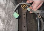 Broken Alternator Lug
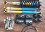 Lift with 3rd Generation Tacoma Coils and Shocks
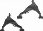 Front lower control arms
 Recommendations for led bulbs for fog lights and low/high beams
 New owner- things to check or must do mods?
ECM, Junction Box 3, +B and +B2 signals, wiring troubleshooting
Discussion in '4th Gen 4Runners (2003-2009)' started by rustyshackleford, Jun 22, 2025 at 12:22 PM.


